|
|
 |
|
"Time Machine" Added on: Fri Apr 07 2000 |
| Page: 1 2 3 4 5 6 |
Blender (cont.)
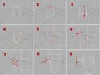
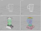
Quick note on modeling the blender jug.
- Create camfer cylinder with eight sides, 5 segments high with a small camfer, the camfer will be the wall thickness.
- Convert to editable mesh, go to sub object polygon mode and select the top eight polygons.
- Using extrude polygon extrude these polygons down leaving space for a base at the bottom. For this example the y axis was used.
- With sub object off taper the cycilner
- With sub object back on select polygon where the top of the handle would be.
- Extruded along the x axis but only a very short didtance.
- Uniform scale the resulting end polygon to the desired size for the thickness for the handle
- Extrude the scaled polygon in steps to the length needed for the handle The steps are needed for shape when it is meshsmoothed at the end of the building process
- Extrude the polygon just under the end downward to continue the shape of the handle
- Use this same process for the lower part of the handle and where the lower handle and upper handle meet weld the vertices
- Meshsmooth the final shape and you're done.
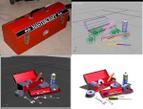
Toolbox
The toolbox was yet another excersise in box modeling. Most of the objects in this section were made up of basic primitives. The rolls of tape were made from two tubes, one for teh tape material and the other for the smaller inner tube of cardboard.
The texture map was mapped using the cylinder gizmo and as a result the streaking that showed on the sides reflected what you'd actually see on a roll of duct tape.
The WD-40 can was made up of a cylinder with a few lathed splines for the top. Finally for the wrenches, they were extruded splines in the shape of wrenches.
 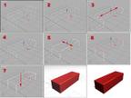
Quick note on modeling the toolbox main container.
- Create box with 3 segments width and length
- Convert to editable mesh, go to sub object vertice mode and select middle vertices lengthwise.
- Non uniform scale vertices contrained along axis of length until they are almost reaching the end vertices. For this example that was Y axis.
- Select middle vertices widthwise
- Non uniform scale vertices contrained along axis of width until they are almost reaching the end vertices. For this example that was X axis..
- Switch to sub object polygon and select the top polygon.
- Extrude polygon down along the hieght of the box until it almost reaches the bottom of the box. In this example this was the Z axis
|
 |
|
|


