|
|
 |
|
"Time Machine" Added on: Fri Apr 07 2000 |
| Page: 1 2 3 4 5 6 |
Lawn Tractor
Modeling
I searched the web and collected numerous images of lawn tractors and chose this one as my reference.
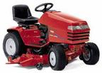
Again, I used this as a modeling reference to model the tractor by eye. I brought in the shopping cart which enabled me to keep a proper scale of the different objects.
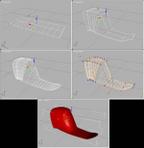
This is where I used mesh smooth for the majority of the modeling.
The smooth fluid shape of the fenders were easy to achieve by using the mesh smooth technique. I found that it was the best way to get smooth shapes. I started with a box, 10 segments on width and 2 segments on height. I converted it to an editable mesh and pushed and pulled the vertices to the shape I wanted and then added the modifier "mesh smooth".
The control points can be wieghted to give an edge a sharper look or a tighter corner. The technique was used with most of the tractor parts.
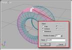
The tires were made with common techniqes as well. I made spline and lathed it for the tire shape. Next I took a small box, edit mesh, shaped it and then mesh smoothed it for a piece of the thread. I then made sure that the thread piece's pivot point was in the centre of the tire using the hierarchy tab and selecting adjust pivot/affect pivot only. I held the shift key and using the rotation tool rotated the tread piece around the z axis (the axis going through the centre of the tire) I had rotation snap on so it was easy to rotate the piece only 5 degrees.
I got the clone options dialog up (right click on the rotation tool in the main tab menu). I set the object to instance and number of copies to 71 as there are 72 / 5 degree parts in 360 (a full rotation). This gave me my thread all around the tire. I cloned this for the other side of the tire and added another lathed spline for the inner (white) part of the wheel. the bolts were made with camfer cylinders with 8 sides and a small fillet.
It's probably a detail I didn't have to add but I couldn't help myself. Besides, one thing to remember in 3D, there is almost never a perfect edge on anything.
|
 |
|
|


