|
Box modeling the basic shape of a car (in this case a SAAB96) |
 |
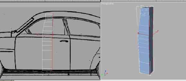
STEP 01 Get a nice blueprint of the car you want to make, ( www.suurland.com is a good site for blueprints) or a photo straight from the side (front or back also helps). And it�s always nice to have some pics of the car from all kind of angles for reference. Put it as a viewport background, (use "match bitmap" and "lock zoom/pan" if you use 3Dsmax) Then it�s time to start modeling, start with a box in the middle of the door, then extrude the top and bottom faces like I did in the following pic. Try to think about how the shape of the car looks from the front/back so you make polygons where the shape demands it. |
 |
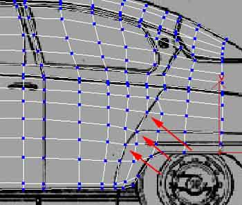
STEP 02 Then select all polygons facing back and extrude them. Remember that you needs edges in the mesh where there�s details on the car, look at the red arrows in the next pic. |
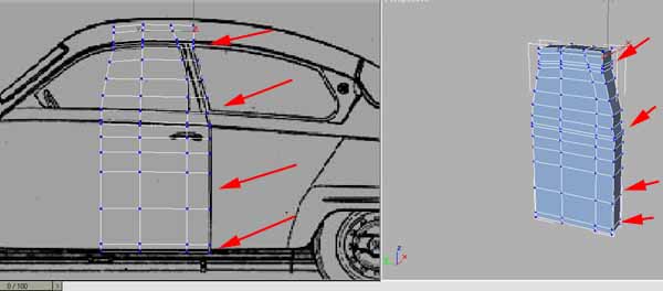 |
STEP 03 Continue to extrude and remember to follow the details, but you dont need the solid edges to follow all details on the car. You can also do as I show with the arrows in the next pic. Because since a face always (in 3dsmax atleast) have 3 sides there�s a hidden edge crossing the polygon (you might have to turn it later on though). |
 |
STEP 04 Then just continue with this untill you got a mesh covering the hole car. |
 |
STEP 05 Now select the polygons so you can extrude them like in next pic. |
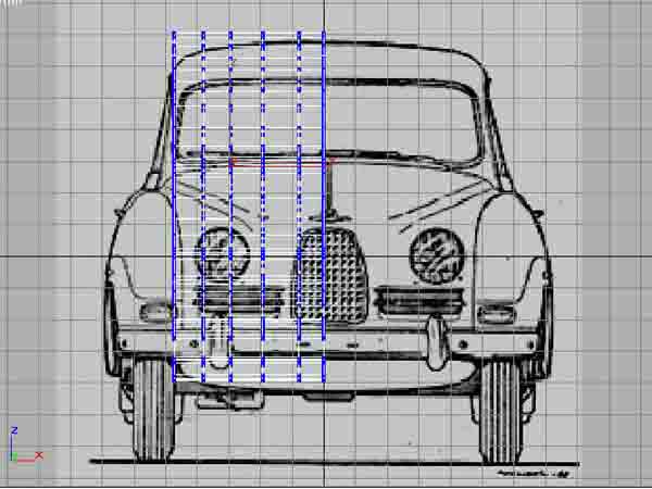 |
STEP 06 Make the big shapes of the car (dont need to be exactly precise yet) like the next pic. Then "mirror copy" and weld them, so you get a "full" car. To weld the 2 parts, select the two middlerows of vertex and then scale them on x-axis, then you can "weld selected" at 0,1 You can then run a "STL-check" to see of you have any errors on the mesh, if you have errors you really need to fix them before you continue. |
 |
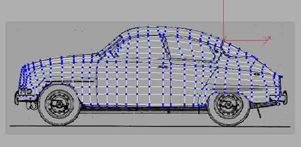
STEP 07 Then add a FFD(box) and set the number of controlers to something like on the next pic. And then shape the car so it looks as much as the background pic as possible. |
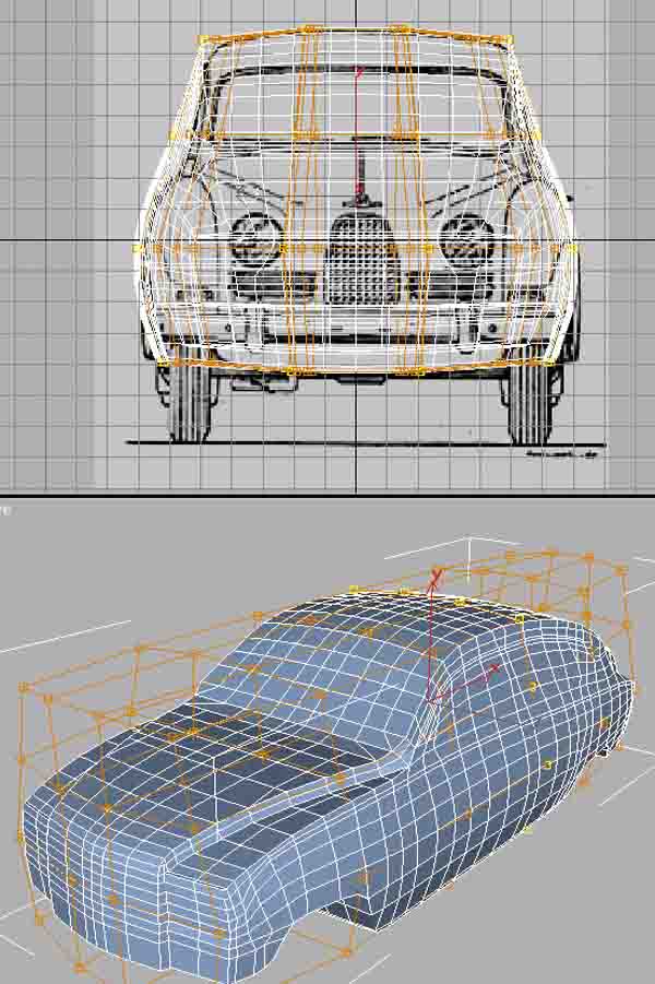 |
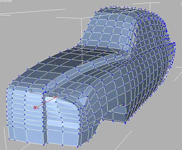
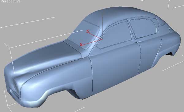
STEP 08 Delete one half of the car and Start working on the shapes. Now you might have to move some vertex back so they are placed at the details you had them on in the start because of the FFD. And you might need to chamfer some edges to make it look good, or you can even weld vertex if it�s like in my case here to many on the front. (remember that the closer or more polys you have the harder it is to get a smooth and soft shape without bumps in it). |
 |
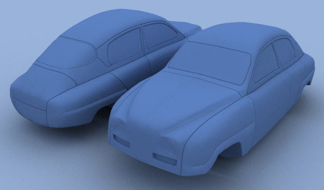
STEP 09 Add a smooth modifyer and set it so you get all round shapes in the same smoothinggroup. Mirror copy the car (you dont need to weld it here) to see the shape better, it�s always good to do this from time to time so you know if youre going in the right direction. |
|
|
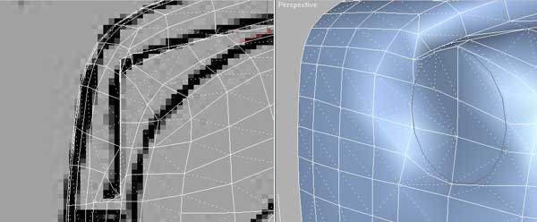
STEP 10 This step is maybe only if youre making a SAAB69, but you can always see it as a tip :) For adding details like the frontlight I use a Circle with about the same amount of steps as i�m planing to use on the mesh around the lights, this way it�s much easiere to get the round shape right. |
 |
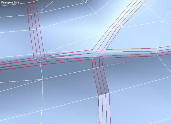
STEP 11 Now select all the edges around the doors, windows and other parts. You might need to remove the "edges only" option in the dispaly menu to see all edges you need to select. |
 |
STEP 12 Then chamfer the selected edges, but dont remove the selection because you should chamfer the edges one more time to make it look like the pic below. You might need to weld some vertexes after this because when you chamfer some edges you get dubble vertexes depending on how many edges is going in to the vertex. :) |
 |
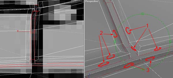
STEP 13 Now select The middle row of polygons of the 3 new ones, and add a "face extrude" modifier and minus extrude it as deep ass you want. Then add a new smoothinggroup to the selected polygones you just -extruded. Now you just need to fix the new polygons smoothinggroups so they match the part of the car they are on, the new faces you extrude need the same smoothinggroup as the part they are the edges of. like the numbers you see on this next pic (They dont need to have different smoothinggroups if they are seperated by the -extruded polygones i just write different numbers to make it clear what i mean). |
 |
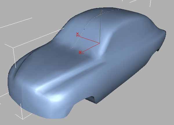
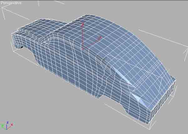
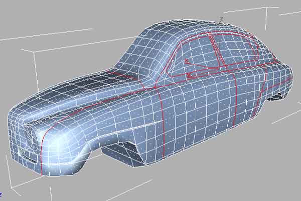
STEP 14 This isnt really a step in the tutorial, it�s just shows what you should have after going through this tutorial. |
 |
Now you can continue to add the details youre car needs, and if youre planing to use mesh smooth i think it works best if you apply "sepparate by smoothing groups". /GRID
Copyright � 1997-2001 GRID |